2.1.1 J₀ Pin Assignment
Pin Assignment of J₀ Connector (M12 A-Coding Binder 09-3491-600-12 - male)
Camera Socket Rear View | Pin | Signal | Level | Cable Standard Color |
|---|---|---|---|---|
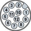 | 1 | Main Power Supply | +24 V | brown |
2 | Common Ground | GND | blue | |
3 | INP 0 or Laser Enable | +5–24 V | white | |
4 | OUT 0 | +24 V | green | |
5 | INP 1 or ENC Z or Trigger Enable | +5–24 V | pink | |
6 | OUT 1 | +24 V | yellow | |
7 | OUT 2 | +24 V | black | |
8 | INP 2 or ENC A or TrigIn | +5–24 V | grey | |
9 | OUT 3 or TrigOut [1] | +24 V | red | |
10 | INP 3 or ENC /B | +5–24 V | purple | |
11 | INP 4 or ENC B | +5–24 V | grey/pink | |
12 | INP 5 or ENC /A | +5–24 V | red/blue/ |
[1]TrigOut only supported at custom OEM versions.
All outputs are high-side switches, 24V, 400mA max.
All inputs and encoder inputs are 5-24V, 3mA, 200kHz max.
Signal Description
Signal | Description |
|---|---|
INP 0 – INP 5 | PLC inputs. |
OUT 0 – OUT 3 | PLC outputs. |
Laser Enable | Hardware safety signal for the activation of the laser, must be set to high to enable |
TrigIn | External trigger for image capture. |
Trigger Enable | External signal to activate capturing, must be set to high for the complete capturing |
ENC A, ENC /A, ENC B, ENC /B, ENC Z | Encoder signals. |
TrigOut | External trigger output, only supported at OEM custom versions; Other versions |

If the Laser Warden is used and no Laser Enable is given, the capture will be done nevertheless but without active laser.

2.1.2 Electrical Specification: Camera Power Supply
Voltage/Current Overview
What | How much |
|---|---|
Nominal Voltage | +24 V |
Absolute Maximum Voltage Limit | +32V |
Minimum recommended Operating voltage | 21.6V |
Maximum recommended Operating voltage | 26.4V |
Operating Current (Typical) | 260mA |
Operating Current (Maximum) | 300mA |
Nominal Power Consumption (Typical) | 6.5W |
Nominal Power Consumption (Maximum) | 7.2W |
2.1.3 Electrical Specification: Digital PLC I/O, Encoder
Electrical Specifications
What | How much |
|---|---|
Separation of PLC/trigger output voltage | PLC outputs supply not separated from power supply |
PLC Input Voltage | +5–24 V |
Input Current (max) | 3mA, Threshold: Positive: +1.3mA typ., Negative: 0.7mA typ. |
PLC Output Voltage | 24V |
PLC Output Current (max) | 4 x 400 mA Max total of all outputs: 1A |
Max Current for 1 Power / PLC connector pin | 400 mA |
Loads | Resistive, inductive and capacitive possible |
Output Protection | Yes: short circuit, overcurrent, temperature |
Power failure detection | Yes, power failure detected if total PLC current > 1A |
If power failure is detected, all PLC outputs may switch off regardless of their output state for hardware protection.
2.1.3.1 Connection of PLC, Encoder inputs VC nano 3D-Z Series

2.1.3.2 Connection of PLC outputs VC nano 3D-Z Series

It is possible to connect the following encoder signals: ENC A, ENC /A, ENC B, ENC /B, ENC Z. There is no connection provided for signal ENC /Z.

Supported Encoder Connection Configurations
ENC A | ENC /A | ENC B | ENC /B | ENC Z | Remarks |
|---|---|---|---|---|---|
X | — | — | — | — | Not recommended |
X | X | — | — | — |
|
X | — | X | — | — | Only recommended for cables < 5m |
X | — | X | — | X | Only recommended for cables < 5m |
X | X | X | X | — | Most noise tolerant |
X | X | X | X | X | Most noise tolerant |
Due to noise and signal bouncing the configuration using only ENC A signal is not recommended.
Pins not used for the encoder can be used as GPIO inputs.
It is possible to swap the signals A and B per software.
The maximum encoder frequency is limited to 200 kHz.
If the ENC Z signal is used, but the full-step resolution of the encoder is not programmed correctly, triggering may stop working after some occurences.
2.1.3.2 Encoder Counter

All internal encoder values represent positions with microstep resolution:
A counter is used internally for counting the full-steps (Bits 31 to 2), whereas the microsteps (Bits 2 to 0) are directly derived from the encoder signals ENC A and ENC B.
The ENC Z signal is detected during microsteps 1 and 2. It resets the full-step counter without resetting the value of the microstep: I.e. the output value during reset can be 0, 1, 2 or 3 depending on the microstep position of the encoder.
If the ENC Z signal is used, the user must program the full-step resolution of the encoder for correct operation, else triggers may not work anymore after some cycles. This number is usually documented at the data sheet of the encoder device. The encoder counts even before the first ENC Z signal is detected. Until then the encoder counter value may be considered as invalid. It is a common practice to calibrate the encoder, moving it to a zero position (reference) first. For your convenience the GPIO input signal 28 is provided indicating that a first ENC Z impulse has been detected. Loss of calibration is indicated if the GPIO input signal 27 is set. This may happen if the ENC Z signal is inconsistent with the full-step resolution. This may occur due to noise, broken cable or a wrong setting for the encoder full-step resolution.
The encoder position at the image trigger is stored in memory for possible later reference.
In case of doubt, the correct programming of the encoder's full-step resolution is verifyable over the GPIO signal 27.
2.1.4 Encoder Trigger

This internal hardware module allows for the generation of triggers every K microsteps (see figure).
It allows to control the spacing of the scanlines with high resolution.
At very low encoder speed the encoder position may occasionally move slightly backwards. In this case there will be no trigger until the encoder reaches the next valid trigger position in forward direction.
Although the encoder trigger is internal, for the image acquisition it acts as like an 'external trigger'. Triggers may be lost during the image acquisition time.
At startup time the system is in an uncalibrated state. This state can also be re-entered when the program 'vcio' is called without the option '-R'. When the first ENC Z signal in positive direction occurs, the system is calibrated, i.e. the encoder position is set to zero plus the current microstep and the next trigger position is set as follows:
trigger position = microstep + trigger increment + trigger offset.
The re-entering done at 'vcio' is a pseudo-calibration like using the Z signal at this encoder position which is all that is necessary for systems without an ENC Z signal.
If the ENC Z signalling is active, each incoming ENC Z signal resets the encoder position counter to zero plus the current microstep, in contrast to the trigger position which is only reset at calibration time.

Example
Given the encoder full-step resolution is 8 and the trigger increment 3.
and the last trigger position of the first revolution is 30. The encoder counter then counts to encoder position 31 and wraps around to 0.
The following trigger signals then occur at positions: 1, 4, 7, …
If increment plus offset is greater than or equals the full-step resolution times 4 trigger signals may never occur.
The encoder does not require an ENC Z signal. Such a system is called an uncalibrated system. It produces the trigger signals relative to a virtual zero which was set at the start of the system and can be set manually by calling 'vcio'.
For systems using the ENC Z signal the situation is similar up to the point where the ENC Z signal occurs. I.e. there may be a number of uncalibrated trigger impulses before the occurrence of the ENC Z signal. After the occurrence of the ENC Z signal the system is calibrated, i.e. the trigger impulses are relative to the absolute zero set by the ENC Z signal at calibration time.
The GPIO input signal 28 is provided indicating that a first ENC Z impulse has been detected.
Always check the direction of the encoder movement if no or not enough trigger impulses occur. You can change the interpretation of the direction via the 'vcio' program.
Warning Sign During image acquisition, additional triggers may be lost.